So I put together this quick and dirty Arduino shutter release for my Canon SLR today.
If you want to to do timed exposures with an SLR camera you usually need something called an intervalometer. Nikon and Canon make versions of this for $100-200. Mine cost around $50 if you include $30 for the Arduino, which I already had. A nice thing about this set up is that unlike an intervalometer, my version allows you to trigger the shutter on the camera for any number of reasons: sensor data, time, signal from an attached computer, etc.
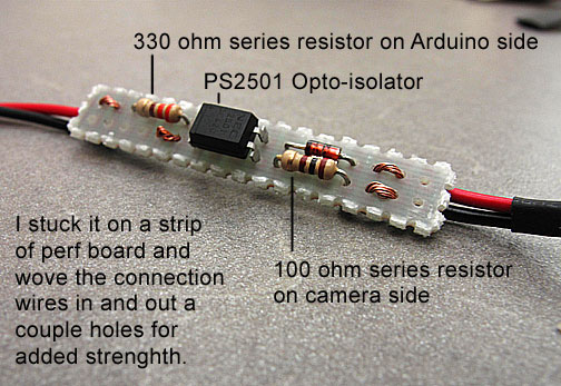
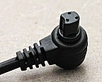
All it is is a generic shutter cable (something like this), a few resistors and an opto-isolator. The opto-isolator is just to be on the safe side. I don’t want to fry my camera. I checked the voltage on the camera and it is somewhere between 3.3 and 5 volts so, if your adventurous, you could try this with a transistor.

Canon and Nikon have different hookups for the shutter cable but they use basically the same set up. There are three pins, one is common, one is shutter, one is focus. If you connect the shutter and common pins the shutter is set off, if you connect the focus and common pins the camera focuses. I didn’t bother with the focu for my version. The camera focuses right before shutter release anyways.
The first couple of times I tried this I fried a few opto-isolators. This is because I didn’t include the resistors. An opto-isolator is basically just a LED and a phototransistor packaged in a IC. The control side(Arduino) turns on the LED, the controlled side (camera) lets current through the phototransistor when the LED is lit, thus the electrical circuits are isolated. Just like you need a resistor in series with your LED you should have one with the opto-isolator. Just to be extra cautious I put a resistor and diode on the camera side of the circuit as well.
To get it to take timed exposures I connected the circuit to pin 13 and GND on the Arduino and plugged the shutter cable into the camera. I modified the “Blink” example sketch that comes with the Arduino IDE to turn on for 0.5 seconds, off for 5 seconds. This results in a basic intervalometer. The device takes a picture every 5 seconds.
There are a bunch of other people creating more complicated devices including this one on Make, but again what I like about this set up is that it is easily adapted to other uses.


